Posts

ImageBuilder and Terraform - Handy Hints

This is for my benefit as much as anybody else, because it took me a while to figure things out: Most of the time when you write for AWS ImageBuilder, the docs tell you to create separate YAML files containing your components.  That's fine, but what if you want to do dynamic substitutions on path and file names?  In that case you probably want to do the definition in the HCL language.  That is, within the actual Terraform code itself. Using S3 One of the more fiddly bits is pulling things from S3 to install on your new instance.  You need to do two things: Have an IAM policy which allows access; and Write the component to do the job Writing the IAM Create a policy resource that looks something like this: resource "aws_iam_policy" "s3_policy" {     name = "s3-policy"     policy = jsonencode(       {           Version = "2012-10-17"           Statement = [             {               Effect = "Allow"               Action = [          

Exploring Solar Power - Are sure the safety is on?

Image
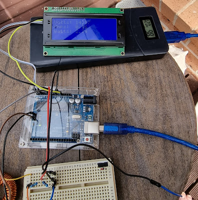
    OK, so we are getting closer to reality here.  Since the last article , I have made some small changes, which helped things out. Firstly, I added a 1000uF/63V filter capacitor to the battery output.  This practically eliminated the serious "hunting" issue that caused the software to rapidly ramp PWM values up and down almost constantly. Next I added two relays to the control circuit. The first is a battery cutoff, which will disconnect the battery if it is above 15V or below 9V, as these would indicate some kind of fault has occurred. The other relay disconnects the solar panel on the same principal.  If either of these events occur, the LCD indicates the nature of the fault. In order for battery monitoring to work effectively, the voltage divider must be located between the relay and the battery .  This way the battery can be reconnected automatically when the fault clears.  I have elected NOT to do this on the solar panel side as an over-voltage condition probably mean

Exploring Solar Power - Let there be smoke!

Image
Last time I introduced my new solar power project.  By the end of that post we were monitoring the power flow from the solar panel to the battery in a simple test environment.  This time we're going to dive in and start trying to control the charge power. What's MPPT? Maximum Power Point Tracking (or Transfer , depending on whom you ask) is a condition where we can transfer the highest power from the solar panel into the battery.  The key here is power, rather than voltage or current on their own.  Remember that power is the product of voltage and current, so it is possible that you will find that perhaps higher current and lower voltage (or vice versa) is the most efficient. What makes this a little problematic is that the peak power point varies constantly depending on the battery state of charge and temperature, so it is not a set and forget operation. This is why the first thing we did was to build a power monitor.  Now we can determine at any point of time, the power bein

Exploring Solar Power - Where do I begin?

Image
I've got a new shed... And even though it's wired for power, my 16x9m shed is going to be powered as much as possible from solar panels and batteries.  Given that I have more than a few computers and radios in there, this is going to be a challenge. The house already has a set of panels and a big inverter, so this is really my own personal R&D project.  For safety, I am not attempting to connect my work to the house wiring, or feed into the grid.  I will be running separate wiring to power this gear. A note on safety Electricity is dangerous.  Contact with live wiring or components can be fatal.  I can't state this clearly enough, electric shocks can, and do kill people.  Batteries contain dangerous chemicals and can give off flammable gasses, which in a confined space can be explosive.  Connecting or disconnecting batteries can cause sparks, which could have very bad side effects. I will detail steps to mitigate these risks, but ultimately it is up to you to be careful

A No-Power Field Strength Meter

Image
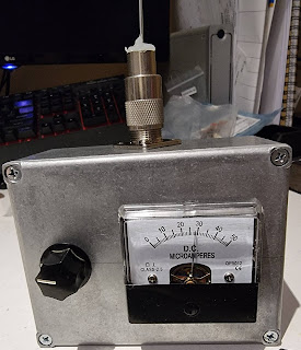
    Before you scoff, this meter does work, and it works well.   Yet it has no battery, no amplifiers, transistors, valves, or even magical elves.   There are just 4 diodes and a capacitor inside the box, and if you have basic hand tools, should be able to make one in about an hour. The circuit is shown in figure 1, and it’s derived from my old RF Design textbook from the early 1980s.   A simple antenna is connected to the SO-239 connector.   A pair of diodes (D1 & D2 rectify the incoming voltage which charges C1.   The variable resistor, VR1 acts as a sensitivity control to allow you to take relative measurements.   Diodes D3 and D4 protect the meter from overloads. Construction There is no PCB or even board required.   D1 and D2 are connected directly to the SO-239.   C1 is soldered to the pins of VR1, while D3 and D4 are connected directly across the meter terminals.   To avoid short circuits, I covered D1 in heat shrink.   Also make sure all ground connections go back to a